Governor Repair

cjmlarson

Mega Poster
WMSTR Lifetime Member
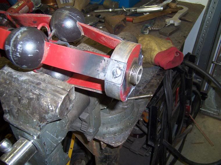
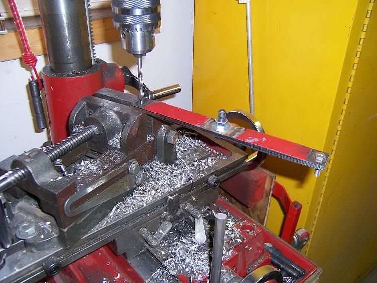
During the long cold spell we have had, the project I have been working on is replacing the flyball springs on a Pickering governor. The springs on this governor are approximately 109 years old, very rusty and seemed to be weak on tension. The first picture is out of order in the process, but will give you the reason I decided to replace them. I consider these to be in poor condition.


100_2683-1.jpg

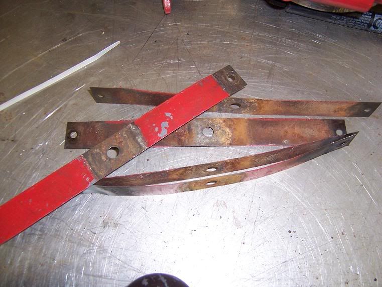
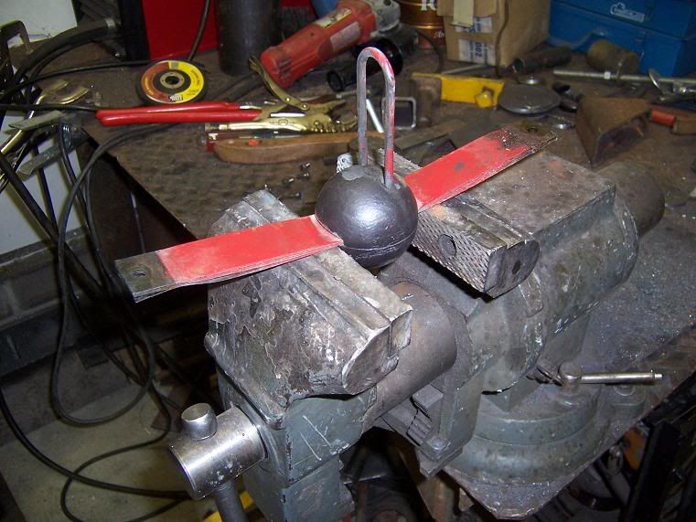
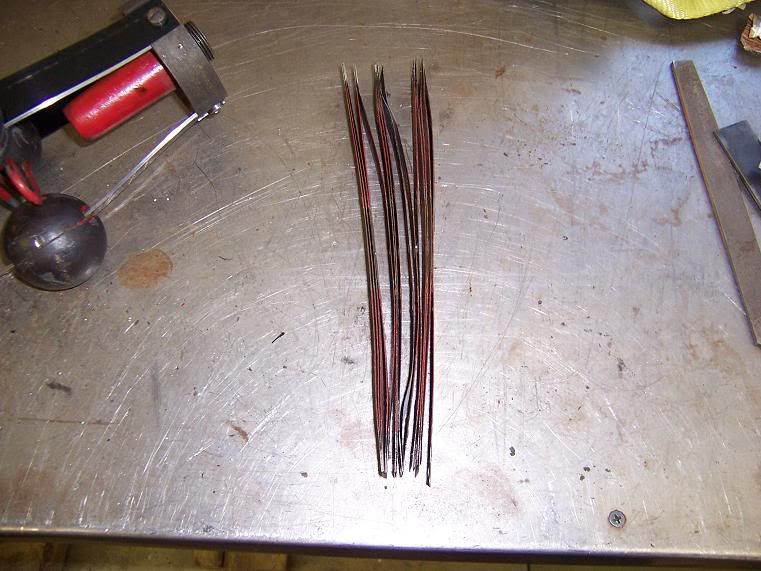
These are the springs that I am changing out. There is a total of 15 altogether.


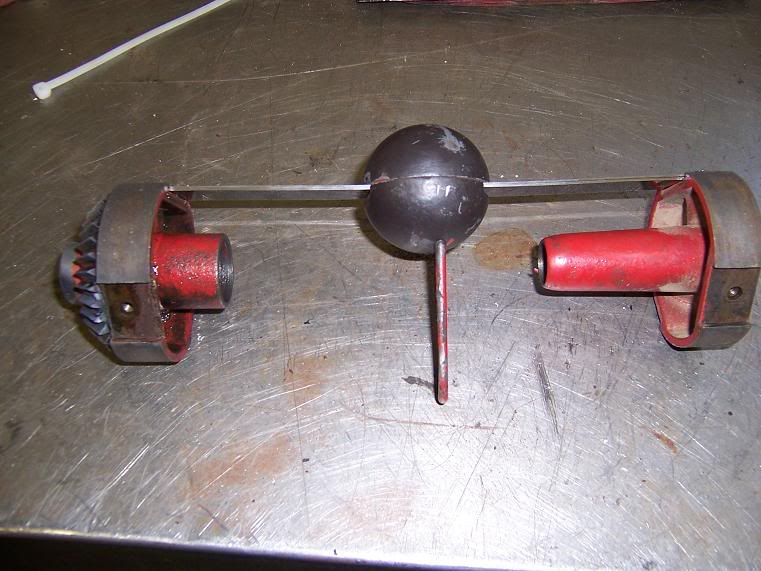
First thing you need to do, is knock the brass rings off both ends of the spring holders. These aren't real tight but you need to be careful not to damage them. They are brass and soft.


100_2672-1.jpg

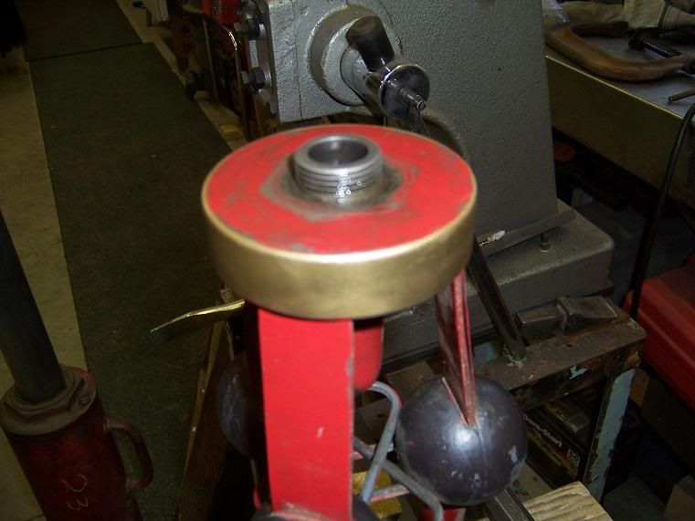
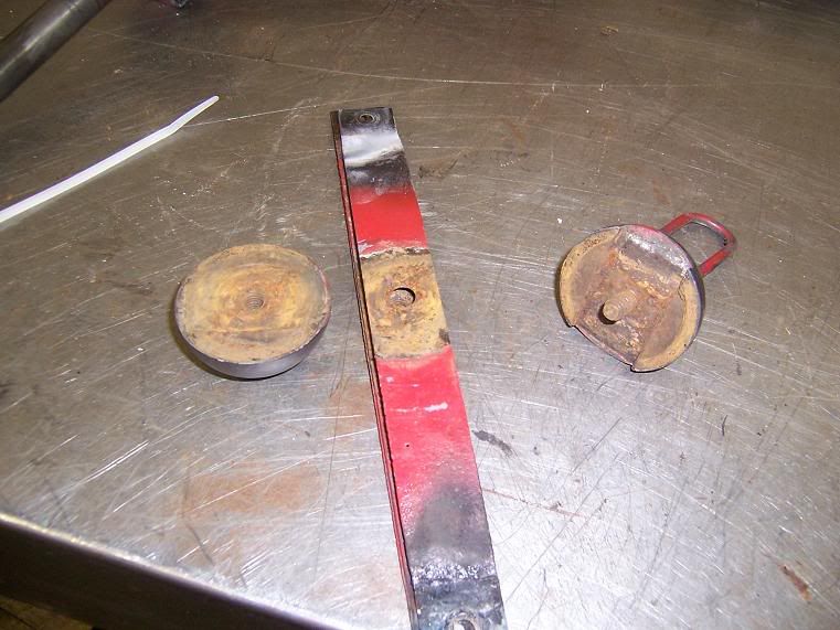
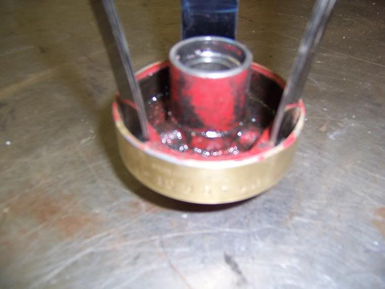
This is how it looks before removing the brass ring.


100_2673-1.jpg

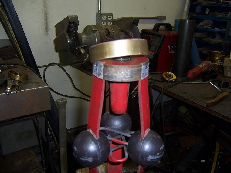
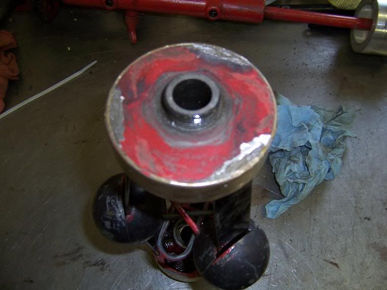
This is what it will look like after removing the brass ring.


100_2671-1.jpg

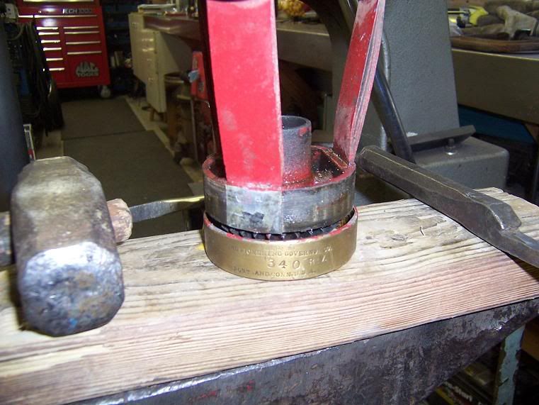
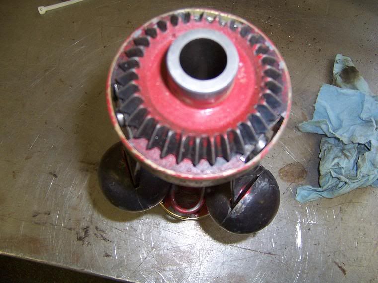
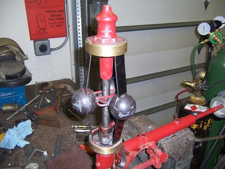
This is the brass ring on the bottom (next to the drive gear).
 
Governor Repair cont.

Next, with the brass rings out of the way, you need to melt the babbit that is in the screw cavity. This screw is what holds the ends of the springs in place. Now you can get to the screw to remove it and the springs will come off of the spring heads.


100_2674-1.jpg

This shows the babbit melted away from the screw head.


With the springs removed from both of the holders, then you need to unscrew the halves of the flyballs. That way you will have your template to cut and drill the new spring steel.


100_2676-1.jpg

I held one half of the flyball in the vise and then used a pipewrench on the other half and unscrewed them.


100_2677-1.jpg

This is what the flyballs look like after splitting them. You will see there is a notch in one half for the springs to fit into. Now you can measure the correct thickness of material that you need at the ends where the small screws go in, as these ends are not rusted. The reason being, is that the babbit kept the moisture away from the spring steel. It is very critical to have the correct thickness material.


100_2679-1.jpg

This is what the new spring steel looks like. It comes in a roll.


Next you need to cut to length the new spring steel out of the correct width and thickness material. The holes you drill in the spring steel need to be accurate, so I used an old spring as a template and drilled all 15 pieces at one time so that they were identical. My recommendation would be to have a couple of real good, sharp drill bits on hand, as this is spring steel and is hard on drill bits.


100_2680-1.jpg

Here I am drilling all 15 pieces at once, so that the holes will all be identical.
 
Hi Clayton,

Great pictures!

How do you know what stiffness of spring steel to order? Or, is spring steel all the same and the stiffness is determined by width and thickness?

If you are careful when the old babbit is melted out, can it be used again?

When do you want test the governor with a Brake?

Later,
Jerry
 
Jerry, The material used is a tempered spring strip that has a very high bounce-back ability.It is blue in color and has a polished finish.You are correct in the width and the thickness determins the strength of the material.

And yes you can use the babbit over again, as for testing........we will wait for above freezing temps I think.

This will be continued soon.
 
cjmlarson;7282 said:
This will be continued soon.

Great thread Clayton! I never had any idea how flyball governors were put together.

Do you think that the rusted / worn out springs were contributing to your "bucky" governor?
 
Mark, I sure hope this takes care off the issues, everything else has been fixed on it.
 
We are now at a point with all springs drilled and cut to length. We are ready to start assembling the governor. You want to make sure that your top and bottom spring holders are clean and oil free, so when it comes time to pour the babbit, they have a good clean surface in the area where the babbit will be poured.


100_2682-1.jpg

I am starting to assemble the springs onto the holder heads with the flyballs installed also.


100_2684-1.jpg

Here I have all the springs and balls assembled and ready to put the brass rings on each end.


100_2686-1.jpg

Just another look at what poor shape the springs were in.


A couple of these pictures are poor because I tried to take them too close, but they're good enough for you to see what's going on.


100_2690-1.jpg

You'll see in this picture the cavities on the end of the springs where the screw holds them to the spring holder. This is where we will pour the babbit in behind the brass ring.


100_2689-1.jpg

This picture shows the very top of the governor with the babbit poured and filed off flush.
 
100_2691-1.jpg

A view of the bottom of the governor before babbit is poured.


100_2692-1.jpg

This picture shows the governor in the upright position. The drive gear is on the bottom showing the cavities poured with babbit.


100_2694-1.jpg

Here's the governor after the rebuild of the flyballs and springs. All that's left is paint. As the picture shows, the springs are tight together with no gaps.
 
Clayton,
I enjoy your posts so much! You always do such a good job of documenting what is taking place with pictures and description.

I have one question. With the tight tolerances used on governors, is there any offset between where the loops that mount in the balls on the springs mount up? You mentioned that all the springs were drilled together and I saw you had them bolted together for the process. I would have guessed that there was a top, center and bottom configuration for these but maybe they aren't quite as tight as I thought.

Thanks for the story,
Nick
 
Nick, you are correct, the safety loops (That is what I call them),they keep the balls from flying out too far, are casted right into the balls themselves. All three balls have the loops cast into them at different hieghts, meaning there is a top, middle and bottom ball. Although you can tip them upside down and eventually get them in the correct position if you were to forget to mark them. I guess I missed that part of the rebuild, I should of shown a better picture of that and had a better description of how that worked.:duh:

That is a very good point because if you do not assemble them correctly the loops will bind and that is not good.
 
Hi Clayton,
Thanks for sharing your experience:thumb:
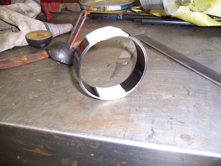
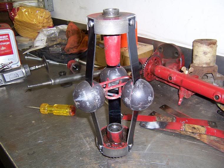
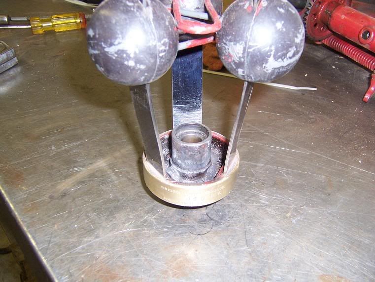
. I'd say a couple of your photos show the "safety loops" and how they're stacked quite well. One question I have is do you have any shots of how you dammed up the cavities to pour the babbit or the process of pouring (guess that's 2 questions)?
As ususal, winter doesn't keep you down. Great thread!....PD
 
P.D. I used the same procedure as when I did the clutch repairs. That, you can see in the Russell thread. To dam up the Babbitt I use Babbitt rite, the only thing is I used a small Ladle due to the total amount of Babitt is minimal. Like a couple of tablespoons for one screw cavity. Now to answer your question, I was all alone when I poured so I did not get pictures of the pour.
 
Back
Top